Expert TFT Display Solutions for Smart Projects | Campus Component
Looking to integrate atft display into your next electronics or IoT project? Campus Component brings expert guidance, reliable sourcing, and practical insights to help engineers, students, and innovators choose the right display technology. A TFT screen delivers sharp colors, fast refresh rates, and excellent visibility, making it perfect for embedded systems, industrial devices, and smart interfaces. In this video, Campus Component explains how a TFT module works, where it is commonly used, and how you can select the best option for your application. If you want dependable components and expert support, connect with Campus Component today and start building.
Bring your electronic innovations to life with a cutting-edge TFT Display from Campus Component. Known for delivering dependable display technologies, Campus Component provides TFT Display modules that balance stunning image quality with robust engineering. Perfect for next-generation control systems, portable devices, and intelligent interfaces, these displays offer exceptional responsiveness and visual precision. Campus Component supports your journey from selection to integration, ensuring you achieve optimal performance and design efficiency. Make your product visually compelling and technologically advanced. Reach out to Campus Component now to find the perfect TFT Display that enhances user experience and strengthens your competitive advantage.
This lcd screen original pin take up 7 I/O parts. If used with Arduino control board, they are not enough to use via connecting with sensors, SD cards, relays, and other modules. Now make it soldering with another adapter module can save 5 I/O ports. Note: We not only provide blue background, but also available with yellow background, please check as below picture: Pricing of them are same. The screen module support backlight power control, which can be set via a jumper cap to connect or disconnect the backlight power supply. Inserting the jumper cap connects the backlight power supply, while removing it disconnects it. Contrast is adjustable; rotating the blue potentiometer clockwise increases contrast, and counter-clockwise decreases it.
Product Specifications
1. Power Supply: +5V 2. Supports I2C protocol 3. Includes backlight and contrast adjustment potentiometer 4. Simpler 4-wire output
Order MOQ
As seen online, MOQ is 100pcs. However they are not fixed, if you also purchase with another products together, each unit MOQ can be less, like 80 or 50 is also acceptable.
This 1.3" round TFT display will be in the shop soon, thanks to this tester, which lets us quickly verify all functionality: We’re reading a display bitmap off of the SD card, displaying it, and then pulsing the backlight. We do this all through the EYESPI connector https://www.adafruit.com/search?q=eyespi and this one is passing just fine. After we package the display, we can stock it in the shop!
Testing ESP programmer board, working on 3.5" Captouch TFT with new ST7796S display & FT6236 touch chips. Board needs redesign for new FPC. Got exciting screen samples (round/bar/rect). Also found great ultra-fine tweezers on DigiKey, for both engineers & entomologists! 🔬🐛🐜
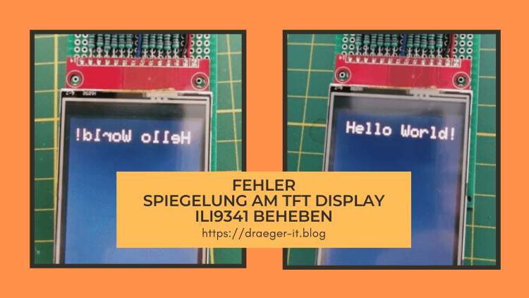
Wenn du das Problem hast, dass du eine gespiegelte Ausgabe auf deinem 2,4" TFT Display (ILI9341) mit der Bibliothek LCDWIKI hast, dann habe ich hier die Lösung für dich.
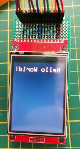
In einem neuen Beitrag möchte ich ein 2,4" TFT Touch Display programmieren, dabei ist mir der Fehler aufgefallen, dass die Ausgabe auf dem Display spiegelverkehrt ist. Eine doch recht lange Google Suche brachte mich dann auf die Lösung, welche ich dir hier gerne auf Deutsch präsentieren möchte.
Fehler - gespiegelte Ausgabe auf ILI9341 mit LCDWIKI
Fehler behoben - gespiegelte Ausgabe auf ILI9341 mit LCDWIKI
Die Lösung findest du auf den beiden nachfolgenden Seiten auf Englisch:
Jedoch behandeln diese eine ganz andere C++ Datei, daher wird man zunächst auf eine falsche Fährte gelockt. Jedoch gibt es diese C++ Datei in den LCDWIKI Bibliotheken nicht bzw. nicht mehr.
Lösung - LCDWIKI gespiegelte Ausgabe ILI9341
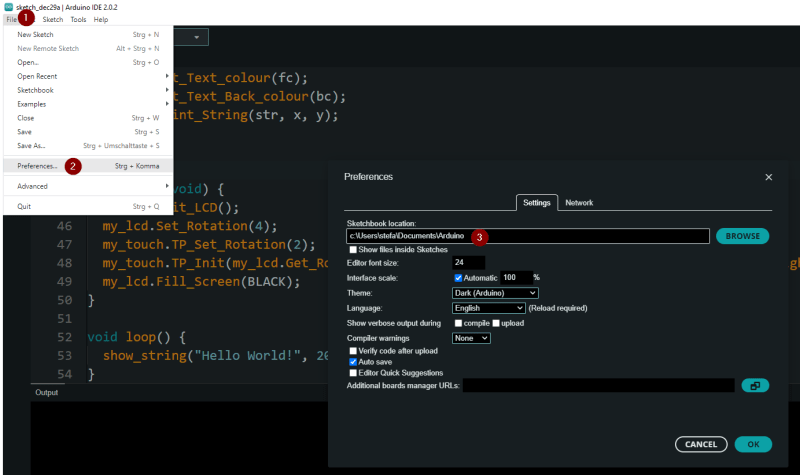
Die Lösung liegt in diesem Falle darin, die Datei “LCDWIKI_SPI.cpp” zu modifizieren. Du findest diese Datei in dem Ordner “C:UsersDocumentsArduinolibrariesLCDWIKI_SPI”. Wenn du jedoch deine Arduino IDE woanders installiert hast, ist dieser Pfad nicht korrekt, den korrekten Pfad findest du in deinen Einstellungen.
Dazu navigierst du über File (1) > Preferences… (2) zu dem Dialog Preferences. Aus diesem kannst du nun das Verzeichnis entnehmen, in welchem die Sketche & Bibliotheken gespeichert werden. Die Bibliotheken findest du wiederum im Unterverzeichnis libraries.
Arduino IDE - Einstellungen für die Ablage von Sketches & Bibliotheken
modifizieren der Datei LCDWIKI_SPI.cpp
Die Zeilen 1257 bis 1271 müssen ausgetauscht werden.
switch (rotation)
{
case 0:
val = ILI9341_MADCTL_MX | ILI9341_MADCTL_BGR; //0 degree
break;
case 1:
val = ILI9341_MADCTL_MV | ILI9341_MADCTL_BGR; //90 degree
break;
case 2:
val = ILI9341_MADCTL_MY | ILI9341_MADCTL_ML |ILI9341_MADCTL_BGR; //180 degree
val = ILI9341_MADCTL_ML | ILI9341_MADCTL_BGR; //0 degree
break;
case 1:
val = ILI9341_MADCTL_MY|ILI9341_MADCTL_MV | ILI9341_MADCTL_BGR; //90 degree
break;
case 2:
val = ILI9341_MADCTL_MY|ILI9341_MADCTL_MX|ILI9341_MADCTL_MH|ILI9341_MADCTL_BGR; //180 degree
break;
case 3:
val = ILI9341_MADCTL_MX | ILI9341_MADCTL_MV | ILI9341_MADCTL_BGR; //270 degree
break;
}
Download der korrigierten Bibliotheken
Wenn du die Datei nicht selber bearbeiten und austauschen möchtest, dann kannst du dir auch die Bibliotheken als gemeinsame ZIP-Datei herunterladen. Du musst nur die ZIP-Datei “LCDWIKI_ILI9341_libs.zip” auf deinem PC entpacken und die darin enthaltenen ZIP-Dateien über deine Arduino IDE importieren.
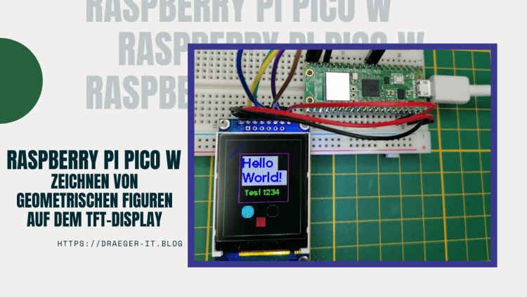
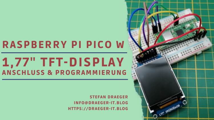
In diesem Beitrag möchte ich dir zeigen, wie du geometrische Figuren am Raspberry Pi Pico W auf einem TFT-Display zeichnen bzw. programmieren kannst.
Zeichnen einfache geometrische Figuren auf dem TFT-Display mit Pi Pico W
In meinem letzten Beitrag Raspberry Pi Pico W mit TFT Display habe ich dir bereits gezeigt, wie du dieses TFT-Display an den Pi Pico anschließen und einen Text ausgeben kannst. Hier soll es nun darum gehen wie du Kreise, Rechtecke usw. zeichnen kannst.
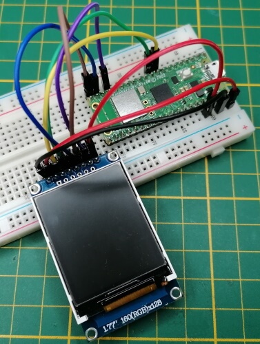
Anschluss des TFT-Displays per SPI an den Raspberry Pi Pico W
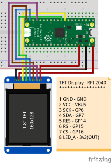
Das Display wird wie folgt am Pi Pico / Pi Pico W angeschlossen:
TFT-DisplayRaspberry Pi Pico / Pico WGNDGNDVCCVBUSSCKGP6SDAGP7RESGP14RSGP15CSGP16LED_A3v3(OUT)Anschluss eines TFT-Displays per SPI an den Raspberry Pi Pico / Pico W
Anschluss eines TFT Displays via SPI an den Raspberry Pi Pico
Schaltung - RP2040 mit TFT Display
Zeichnen von geometrischen Figuren
Mit dem hier verwendeten Modul können von Hause aus nicht direkt einfache geometrische Figuren gezeichnet werden. Das Modul bietet lediglich die Funktion zum Zeichnen eines Punktes, gefülltes Rechteck sowie eines Textes. Mit der Funktion zum Zeichnen eines Punktes / Pixels können wir uns jedoch die Funktionen für Kreise, Rechtecke etc. selber programmieren, was wir hier nun machen wollen.
Wenn du die erweiterte Version von meinem GitHub Repository verwendest, dann hast du die nachfolgenden Funktionen bereits enthalten!
#Paru-Tech Solutions We have many more models of Laptops, desktops, and All in one Pc at an affordable price. If you want to Buy please feel free to call or what’s app. 7410107711, 7410106611


