This high-quality image highlights the premium finish and vibrant clarity of an advanced oled display showcasing why this technology is preferred in modern electronics, smart devices, and industrial applications. The sharp contrast, deep blacks, and energy efficiency visible in the image reflect the performance standards delivered by Campus Component. Customers searching for reliable quality along with a competitive oled display price will find Campus Component to be a trusted partner that balances innovation with affordability. Every product offered by Campus Component is carefully sourced to meet real-world usage demands while maintaining long-term reliability. If you are planning to upgrade your display solutions or integrate cutting-edge visuals into your project, connect with Campus Component today and experience display technology that truly stands out.
Im letzten Beitrag habe ich dir gezeigt, wie du das OLED Display mit Drehregler (EC11) am Arduino anschließt und programmierst. In diesem Artikel gehen wir einen Schritt weiter: Wir bauen ein komplettes Menüsystem, das du mit dem Drehregler bequem durchscrollen und über die Tasten bedienen kannst. So lassen sich Werte einstellen, Funktionen aktivieren oder ganze Untermenüs aufrufen – ganz wie bei professionellen Geräten.
Hinweis von mir: Die mit einem Sternchen (*) markierten Links sind Affiliate-Links. Wenn du über diese Links einkaufst, erhalte ich eine kleine Provision, die dazu beiträgt, diesen Blog zu unterstützen. Der Preis für dich bleibt dabei unverändert. Vielen Dank für deine Unterstützung!
Aufbau der Schaltung
Bevor wir mit dem Programm beginnen, schauen wir uns den Aufbau der Schaltung an. Das OLED-Display wird über die I²C-Schnittstelle mit dem Arduino verbunden, während der EC11-Drehregler zwei digitale Pins zur Erkennung der Drehrichtung und einen weiteren Pin für die Tasterfunktion (Push) nutzt. Über diese Kombination lässt sich später bequem durch das Menü navigieren und eine Auswahl treffen.
Schaltung - Arduino mit OLED Display und Rotary Encoder Modul und LEDs auf Breadboard
Zusätzlich sind auf dem Board noch zwei separate Taster verbaut – Confirm und Back –, die wir ebenfalls in unser Menüsystem integrieren können. So lässt sich das Menü nicht nur über den Drehregler bedienen, sondern bei Bedarf auch über klassische Tasten steuern. Die vier farbigen LEDs werden schließlich an eigene Pins angeschlossen und zeigen den aktuellen Zustand der jeweiligen Menüpunkte an.
Schaltung - Arduino UNO - OLED Display Rotary Encoder
Quellcode
Nachdem der Aufbau steht, kümmern wir uns nun um die Programmierung.
Damit der Arduino den Drehregler (EC11) korrekt auslesen und das OLED-Display mit SH1106-Treiber ansteuern kann, benötigen wir zwei Bibliotheken:
- Bibliothek zum Auslesen des Rotary Encoders Für den Rotary Encoder gibt es verschiedene Bibliotheken. Ich habe mit der Variante von CarlosSiles67 sehr gute Erfahrungen gemacht. Diese kannst du direkt von GitHub unter 👉 https://github.com/CarlosSiles67/Rotary als ZIP-Datei herunterladen und anschließend über den Bibliotheksverwalter in der Arduino IDE installieren. - Bibliothek zum Ansteuern des Displays Das verwendete OLED-Display nutzt den SH1106-Treiberchip, weshalb wir die passende Adafruit_SH110x-Bibliothek benötigen. Du findest sie entweder auf GitHub unter 👉 Adafruit / Adafruit_SH110x oder ganz bequem über den Bibliotheksverwalter der Arduino IDE durch die Suche nach „Adafruit SH110x“.
Sind beide Bibliotheken installiert, kann der folgende Code direkt auf deinen Arduino geladen werden.
/******************************************************* * Projekt: Interaktive Menüs am Arduino * Titel: OLED Display mit Drehregler (EC11) – Menüsteuerung * Beschreibung: * Dieses Beispiel zeigt, wie man mit einem EC11-Drehregler * (Rotary Encoder) und einem OLED-Display (SH1106) ein * interaktives Menü erstellt. * Durch Drehen des Reglers navigierst du durch die Menüpunkte, * und mit einem Druck auf den Encoder schaltest du die jeweilige LED ein oder aus. * * Verwendete Hardware: * - Arduino (UNO, Nano oder kompatibel) * - OLED-Display mit SH1106-Treiber (I2C) * - EC11 Drehregler mit Push-Button * - 4 LEDs (blau, gelb, rot, grün) * * Weitere Informationen und Anleitung: * https://draeger-it.blog/interaktive-menues-am-arduino-so-steuerst-du-dein-oled-display-mit-einem-drehregler/ * * Autor: Stefan Draeger *******************************************************/ #include #include #include #include #include // — LED Pins definieren — #define ledBlau 11 #define ledGelb 10 #define ledRot 9 #define ledGruen 8 // — Zusätzliche Buttons (optional) — #define confirmBtn 7 #define backBtn 6 // — Drehregler Pins — #define tra 4 #define trb 3 #define push 2 // Rotary-Objekt initialisieren Rotary rotary = Rotary(tra, trb, push); // — OLED Display Setup — #define i2c_Address 0x3c Adafruit_SH1106G display = Adafruit_SH1106G(128, 64, &Wire, -1); // — Menüdefinition — String menu = { “LED blau”, “LED gelb”, “LED rot”, “LED gruen” }; // — Status und Pins der LEDs — int ledStatus = { 0, 0, 0, 0 }; int ledPins = { ledBlau, ledGelb, ledRot, ledGruen }; // — Menüposition — int menuIndex = 0; void setup() { Serial.begin(9600); display.begin(i2c_Address, true); display.clearDisplay(); // LEDs als Ausgang konfigurieren pinMode(ledBlau, OUTPUT); pinMode(ledGelb, OUTPUT); pinMode(ledRot, OUTPUT); pinMode(ledGruen, OUTPUT); // Erstes Menü anzeigen displayMenu(); } /** * Anzeige des Menüs auf dem OLED-Display * Der aktuell gewählte Menüpunkt wird invertiert dargestellt. * Links neben jedem Eintrag wird ein Kreis angezeigt, * der den Status der jeweiligen LED symbolisiert. */ void displayMenu() { int menuOffsetX = 30; int menuOffsetY = 10; display.clearDisplay(); display.setTextSize(1); display.drawRect(2, 2, 126, 62, SH110X_WHITE); // Rahmen for (int i = 0; i invertierte Darstellung if (menuIndex == i) { display.setTextColor(SH110X_BLACK); display.fillRect(menuOffsetX - 2, y - 2, 60, 11, SH110X_WHITE); } else { display.setTextColor(SH110X_WHITE); } // Statuskreis zeichnen display.drawCircle(menuOffsetX - 10, y + 3, 5, SH110X_WHITE); if (ledStatus == 1) { // LED an -> kleiner Punkt im Kreis display.fillCircle(menuOffsetX - 10, y + 3, 2, SH110X_WHITE); } // Menütext ausgeben display.println(menu); } display.display(); } /** * Aktualisiert den Zustand der LEDs entsprechend der gespeicherten Werte */ void updateLEDs() { for (int index = 0; index < 4; index++) { digitalWrite(ledPins, ledStatus); } } /** * Hauptschleife: * - Drehen des Reglers bewegt den Auswahlindex im Menü * - Drücken des Reglers toggelt die jeweilige LED */ void loop() { unsigned char currentPosition = rotary.process(); bool action = false; // Nach unten scrollen (Drehung im Uhrzeigersinn) if (currentPosition == rotary.clockwise()) { if (menuIndex 0) { menuIndex–; action = true; } } // Druck auf den Drehregler -> LED toggeln if (rotary.buttonPressedReleased(20)) { ledStatus = ledStatus == 0 ? 1 : 0; action = true; } // Wenn sich etwas geändert hat -> neu zeichnen und LEDs updaten if (action) { displayMenu(); updateLEDs(); } }
In diesem Beitrag zeige ich dir, wie du mit wenig Hardware eine kleine Arduino Slotmaschine programmierst, die auf einem 1,3" OLED-Display läuft. Gesteuert wird das Ganze per Tastendruck: drei Symbole rotieren unabhängig voneinander und bleiben nach kurzer Zeit stehen – fast wie bei einer echten Slotmaschine.
Als Mikrocontroller verwende ich hier den neuen Arduino Nano R4, da er bei mir ohnehin im Einsatz ist. Du kannst das Projekt aber genauso gut mit jedem anderen Arduino Nano umsetzen – egal ob Nano V3, Nano IoT, einem ESP32 im Nano-Format oder einem vergleichbaren Board.
Das Projekt ist einfach nachzubauen, macht Spaß und eignet sich perfekt, um erste Erfahrungen mit Displaysteuerung und kleinen Animationen auf dem Arduino zu sammeln.
🔔 Hinweis: Dieses Projekt zeigt eine kleine Slotmaschine auf dem Arduino – ganz ohne Einsatz von Geld, nur zum Spaß und Lernen. Glücksspiel ist keine gute Sache und birgt ernsthafte Risiken. Wenn du von Glücksspielsucht betroffen bist oder dir Sorgen machst, findest du unter der kostenfreien Hotline des Bundesinstituts für öffentliche Gesundheit Unterstützung: 📞 0800 – 137 27 00
Benötigte Bauteile
Für den Nachbau der kleinen Arduino-Slotmaschine brauchst du nur wenige Standardkomponenten:
Hinweis für Arduino Nano R4 Nutzer: Wenn du – wie ich – den Arduino Nano R4 verwenden möchtest, benötigst du zusätzlich zwei 4,7 kΩ Widerstände. Diese dienen als I²C Pull-Ups und verbinden die Leitungen SDA und SCL mit VCC, damit die Kommunikation mit dem OLED-Display zuverlässig funktioniert. (siehe NEU! Arduino Nano R4: Der I2C-Fix, den dir keiner sagt (Pull-Ups!))
Hinweis von mir: Die mit einem Sternchen (*) markierten Links sind Affiliate-Links. Wenn du über diese Links einkaufst, erhalte ich eine kleine Provision, die dazu beiträgt, diesen Blog zu unterstützen. Der Preis für dich bleibt dabei unverändert. Vielen Dank für deine Unterstützung!
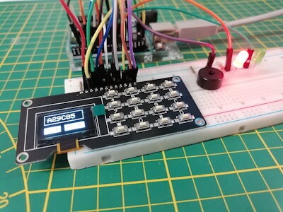
👉 Ich baue die Schaltung zunächst auf dem Breadboard auf. Sobald alles funktioniert, nutze ich das FlexCase von makers-gonna-make.de, für das ich mir ein eigenes Plate entworfen habe, auf dem sowohl das Display als auch der Taster Platz finden.
Arduino Slotmachine im FlexCase von makersgonnamake
Aufbau der Schaltung auf einem Breadboard
Für den ersten Testaufbau wird die Slotmachine-Schaltung ganz einfach auf einem Breadboard realisiert. So kannst du schnell prüfen, ob Display, Taster und Buzzer wie gewünscht funktionieren, bevor du später vielleicht ein Gehäuse oder ein FlexCase verwendest.
Schaltung - Arduino Nano R4 mit OLED-Display - Taster und Piezo Buzzer Verdrahtung - OLED-Display (SH1106, I²C) - VCC → 5V am Arduino Nano R4 - GND → GND - SDA → A4 (I²C-Datenleitung) - SCL → A5 (I²C-Taktleitung) - Pull-Up-Widerstände (nur beim Nano R4 nötig) - 4,7 kΩ von SDA nach VCC - 4,7 kΩ von SCL nach VCC - Taster - ein Pin → D2 am Arduino (mit INPUT_PULLUP im Code) - anderer Pin → GND - Buzzer - ein Pin → D3 am Arduino - anderer Pin → GND Hinweis
Der Taster wird hier gegen GND geschaltet und im Sketch mit INPUT_PULLUP konfiguriert. Dadurch sparst du dir einen externen Widerstand.
Symbole für die Slotmachine
Für unsere Slotmachine benötigen wir Icons – jeweils ein 🍀 Kleeblatt, ein ❤️ Herz, 🍒 Kirschen und eine Sieben. Diese Symbole werden als XBM-Bitmaps im Arduino-Sketch eingebunden und anschließend mit drawXBitmap() auf dem OLED-Display dargestellt.
Natürlich kannst du auch eigene Icons erstellen und verwenden – deiner Kreativität sind keine Grenzen gesetzt. Wie du ein beliebiges PNG-Bild in das XBM-Format umwandelst, habe ich hier Schritt für Schritt erklärt: 👉 XBM Bitmaps für Arduino Displays: So geht’s Schritt für Schritt
Bevor wir mit der eigentlichen Slotmachine beginnen können, müssen wir zunächst das OLED-Display ansteuern. Dafür benötigen wir die passende Bibliothek.
Bibliothek installieren
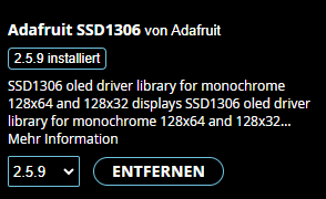
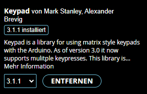
Da ich ein 1,3″ OLED-Display mit SH1106G-Treiberchip verwende, nutze ich die Adafruit SH110X Library. Diese installierst du bequem über den Bibliotheksverwalter der Arduino IDE:
- links im Menü den Eintrag “Bibliotheksverwalter” auswählen (drittes Icon von oben) - Nach „Adafruit SH110X“ suchen - Bibliothek installieren (die Adafruit GFX Library wird automatisch als Abhängigkeit mitinstalliert) Bibliothek - Adafruit SH110X in der Arduino IDE Bibliothek - Adafruit GFX in der Arduino IDE
Solltest du jedoch ein OLED-Display mit SSD1306 Chip haben, so musst du nach Adafruit SSD1306 suchen.
Bibliothek einbinden
Nachdem die beiden Bibliotheken installiert wurden, können diese wiefolgt eingebunden und verwendet werden:
Damit ist dein Projekt vorbereitet, um Grafiken, Text und später auch die Slot-Symbole auf dem OLED-Display darzustellen.
Snipets aus dem Code
Nachfolgend möchte ich dir einige besondere Code-Snippets erläutern. Im Grunde ist der Aufbau und Ablauf der Slotmachine recht einfach, dennoch gibt es ein paar spannende Stellen, die man sich genauer ansehen sollte.
Taster per Interrupt
Der Taster ist am Interrupt-Pin D2 angeschlossen. Das ermöglicht, die Eingabe sofort zu registrieren – unabhängig davon, was im loop() gerade passiert. So bleibt die Slotmachine reaktionsschnell und du musst den Taster nicht ständig in der Schleife abfragen.
// Pin für den Taster (gegen GND, wir nutzen INPUT_PULLUP) #define taster 2 void setup(){ … // Interrupt auf den Taster legen: // CHANGE = löst bei Flanke (HIGH->LOW und LOW->HIGH) aus. // Wir schützen uns gegen Doppeltrigger mit TIME_BETWEEN_PRESS. attachInterrupt(digitalPinToInterrupt(taster), stoppSlotMachine, CHANGE); } // ISR (Interrupt Service Routine) für den Taster. // Achtung: ISR sollte kurz sein – hier nur Status erhöhen // und eine einfache Sperrzeit gegen Prellen/Mehrfachtrigger prüfen. void stoppSlotMachine() { long currentMillis = millis(); if (currentMillis > (lastButtonPress + TIME_BETWEEN_PRESS) && !endGame) { currentIndex++; // nächste Walze wird „fixiert“ lastButtonPress = currentMillis; } } Zeichnen der Walzen
Die drei Walzen (Slots) werden in einer eigenen Funktion gezeichnet. Der Funktion wird die jeweilige Position (0, 1 oder 2) und der Index des Bildes aus dem Array epd_bitmap_allArray übergeben. So kannst du an einer Stelle zentral steuern, welches Symbol wo auf dem Display landet.
// Pointer-Array auf alle Symbol-Bitmaps (in PROGMEM abgelegt) // Reihenfolge: 0=Kleeblatt, 1=Herz, 2=Kirschen, 3=Sieben const unsigned char* const epd_bitmap_allArray PROGMEM = { epd_bitmap_kleeblatt, epd_bitmap_herz, epd_bitmap_kirschen, epd_bitmap_seven }; // Zeichnet einen Symbol-Rahmen + Bitmap an Position 0/½. // ‘bild’ ist der Index im epd_bitmap_allArray (0..3) void zeichneXBmp(int position, int bild) { // Layout-Offsets (Rahmen und Bild leicht eingerückt) int xOffsetRahmen = 4; int yOffsetRahmen = 20; int xOffsetBild = 4; int yOffsetBild = 22; // X-Positionen: drei Spalten im Abstand von 38 Pixeln int rahmenXPos = xOffsetRahmen + (position * 38); int bildXPos = xOffsetBild + (position * 38); // Rahmen zeichnen (35x35, mit Radius 5) display.drawRoundRect(rahmenXPos + 6, 20, 35, 35, 5, SH110X_WHITE); // Bitmap zeichnen // HINWEIS: Wenn dein Pointer-Array tatsächlich in PROGMEM liegt und // du Probleme bekommst, auf AVR-Boards besser so lesen: // const unsigned char* bmp = (const unsigned char*)pgm_read_ptr(&epd_bitmap_allArray); // display.drawBitmap(bildXPos + 6, 22, bmp, img_width, img_height, SH110X_WHITE); display.drawBitmap(bildXPos + 6, 22, epd_bitmap_allArray, img_width, img_height, SH110X_WHITE); } Zufallszahl für Symbole
Das Bild, das beim Rotieren einer Walze angezeigt wird, wird per Zufallszahl ermittelt:
int randNumber = random(NUM_ELEMENTS);
In meinem Fall gibt es 4 Symbole (Kleeblatt, Kirsche, Herz und Sieben), also Zufallszahlen von 0–3.
Die Anzahl lässt sich beliebig erweitern – einfach weitere Bitmaps hinzufügen und NUM_ELEMENTS anpassen. Da das XBM-Format sehr speicherschonend ist, kannst du problemlos auch 6, 8 oder noch mehr Symbole verwenden.
// Merker, welches Symbol auf welcher Walze zuletzt liegt // slot = linke Walze, slot = mittlere, slot = rechte int slot = { -1, -1, -1 }; // Wie viele Walzen sind bereits per Tastendruck gestoppt? // -1 = noch keine, 0 = erste gestoppt, 1 = zweite gestoppt, 2 = alle drei gestoppt int currentIndex = -1; void setup() { … // Zufallszahlengenerator initialisieren randomSeed(analogRead(0)); … } // Dreht die noch nicht gestoppten Walzen „weiter“: // Für jede nicht fixierte Walze: löschen, zufälliges Symbol wählen, // merken und neu zeichnen. Aktualisiert die Anzeige und wartet kurz. void rotiereBild() { for (int i = 0; i = i) { // Walze i ist bereits gestoppt -> überspringen continue; } loescheBild(i); // altes Symbol entfernen display.display(); int randNumber = random(NUM_ELEMENTS); // 0..3 slot = randNumber; // Symbol merken (für Ergebnisprüfung) zeichneXBmp(i, randNumber); // neues Symbol zeichnen } display.display(); // alle Änderungen anzeigen delay(750); // Rotationsgeschwindigkeit (größer = langsamer) } Quellcode
Nachfolgend der Quellcode zum Download und zum kopieren.
Mini-Spiel: Arduino SlotmachineHerunterladen Datei: arduino_slotmachine.ino /***************************************************** * Titel: Arduino Slotmachine – Mini-Spiel auf dem OLED! * * Beschreibung: * Dieses Projekt zeigt eine kleine Slotmaschine auf * einem 1,3" I²C-OLED (SH1106). Drei Walzen rotieren * mit zufälligen Symbolen (Kleeblatt, Herz, Kirschen, * Sieben). Mit jedem Tastendruck stoppst du die nächste * Walze. Gewinn/Falsch-Ende wird auf dem Display * angezeigt und per Buzzer-Sound quittiert. * * Voller Projekt-Artikel: * https://draeger-it.blog/gluecksspiel-im-mini-format-slotmaschine-mit-arduino-oled-bauen/ * * Hardware: * - Arduino Nano R4 (andere kompatible Boards möglich) * - 1,3" OLED (SH1106, I²C, Adresse 0x3C) * - Taster an D2 (gegen GND, INPUT_PULLUP) * - Buzzer an D3 * - Beim Nano R4: 2x 4,7 kΩ Pullups für SDA/SCL auf VCC * * Bibliotheken (über Bibliotheksverwalter installieren): * - Adafruit_GFX * - Adafruit_SH110X *****************************************************/ #include #include #include #include // — eigene Assets (Bitmaps & Sounds) — #include “kleeblatt.h” #include “herz.h” #include “kirsche.h” #include “sieben.h” #include “winner_tone.h” #include “fail_tone.h” // I²C-Adresse des SH1106-Displays (typischerweise 0x3C) #define i2c_Address 0x3c // Pin für den Taster (gegen GND, wir nutzen INPUT_PULLUP) #define taster 2 // Pin für den Buzzer (aktiv per HIGH) #define BUZZER_PIN 3 // Größe der XBM-Symbole (alle 32x32 Pixel) #define img_width 32 #define img_height 32 // Display-Objekt: 128x64 Pixel, I²C, kein Reset-Pin Adafruit_SH1106G display = Adafruit_SH1106G(128, 64, &Wire, -1); // Anzahl der Symbol-Bitmaps const int NUM_ELEMENTS = 4; // Pointer-Array auf alle Symbol-Bitmaps (in PROGMEM abgelegt) // Reihenfolge: 0=Kleeblatt, 1=Herz, 2=Kirschen, 3=Sieben const unsigned char* const epd_bitmap_allArray PROGMEM = { epd_bitmap_kleeblatt, epd_bitmap_herz, epd_bitmap_kirschen, epd_bitmap_seven }; // Wie viele Walzen sind bereits per Tastendruck gestoppt? // -1 = noch keine, 0 = erste gestoppt, 1 = zweite gestoppt, 2 = alle drei gestoppt int currentIndex = -1; // Zeitverwaltung für einfache Entprellung / Blockzeit zwischen Tastendrücken long lastButtonPress = -1; const long TIME_BETWEEN_PRESS = 500; // ms // Merker, welches Symbol auf welcher Walze zuletzt liegt // slot = linke Walze, slot = mittlere, slot = rechte int slot = { -1, -1, -1 }; // Signalisiert, dass eine Runde abgeschlossen ist bool endGame = false; void setup() { Serial.begin(9600); // Taster-Pin auf internen Pullup schalten pinMode(taster, INPUT_PULLUP); // Interrupt auf den Taster legen: // CHANGE = löst bei Flanke (HIGH->LOW und LOW->HIGH) aus. // Wir schützen uns gegen Doppeltrigger mit TIME_BETWEEN_PRESS. attachInterrupt(digitalPinToInterrupt(taster), stoppSlotMachine, CHANGE); // Buzzer-Pin als Ausgang pinMode(BUZZER_PIN, OUTPUT); // Zufallszahlengenerator initialisieren randomSeed(analogRead(0)); // Display starten und kurzen Boot-Screen zeigen delay(250); display.begin(i2c_Address, true); display.display(); delay(2000); // Erste Runde vorbereiten startGame(); } // Setzt eine neue Runde auf: Anzeige leeren, Überschrift zeichnen, // drei Rahmen/Symbole initial zeigen, Status zurücksetzen. void startGame() { Serial.println(“startGame”); currentIndex = -1; slot = slot = slot = -1; endGame = false; display.clearDisplay(); display.setTextColor(SH110X_WHITE); display.setTextSize(1); display.setCursor(9, 8); display.println(F(“Arduino Slotmachine”)); // Anfangsanzeige: drei Symbole (0,1,2) ins Raster zeichnen zeichneXBmp(0, 0); zeichneXBmp(1, 1); zeichneXBmp(2, 2); display.display(); endGame = false; } // ISR (Interrupt Service Routine) für den Taster. // Achtung: ISR sollte kurz sein – hier nur Status erhöhen // und eine einfache Sperrzeit gegen Prellen/Mehrfachtrigger prüfen. void stoppSlotMachine() { long currentMillis = millis(); if (currentMillis > (lastButtonPress + TIME_BETWEEN_PRESS) && !endGame) { currentIndex++; // nächste Walze wird „fixiert“ lastButtonPress = currentMillis; } } // Zeichnet einen Symbol-Rahmen + Bitmap an Position 0/½. // 'bild’ ist der Index im epd_bitmap_allArray (0..3) void zeichneXBmp(int position, int bild) { // Layout-Offsets (Rahmen und Bild leicht eingerückt) int xOffsetRahmen = 4; int yOffsetRahmen = 20; int xOffsetBild = 4; int yOffsetBild = 22; // X-Positionen: drei Spalten im Abstand von 38 Pixeln int rahmenXPos = xOffsetRahmen + (position * 38); int bildXPos = xOffsetBild + (position * 38); // Rahmen zeichnen (35x35, mit Radius 5) display.drawRoundRect(rahmenXPos + 6, 20, 35, 35, 5, SH110X_WHITE); // Bitmap zeichnen // HINWEIS: Wenn dein Pointer-Array tatsächlich in PROGMEM liegt und // du Probleme bekommst, auf AVR-Boards besser so lesen: // const unsigned char* bmp = (const unsigned char*)pgm_read_ptr(&epd_bitmap_allArray); // display.drawBitmap(bildXPos + 6, 22, bmp, img_width, img_height, SH110X_WHITE); display.drawBitmap(bildXPos + 6, 22, epd_bitmap_allArray, img_width, img_height, SH110X_WHITE); } // Löscht den Bereich einer Walze (füllt den Rahmen schwarz) void loescheBild(int position) { int xOffsetRahmen = 4; int yOffsetRahmen = 20; int rahmenXPos = xOffsetRahmen + (position * 38); display.fillRoundRect(rahmenXPos + 6, 20, 35, 35, 5, SH110X_BLACK); } // Dreht die noch nicht gestoppten Walzen „weiter“: // Für jede nicht fixierte Walze: löschen, zufälliges Symbol wählen, // merken und neu zeichnen. Aktualisiert die Anzeige und wartet kurz.
On the penultimate night and New Year’s Eve, we’re making a quick Qwiic board—this is an I2C breakout for transparent OLED displays. We’ve had the display in our ‘in progress’ bin for a few years but finally sat down to finish it tonight. We’re experimenting with a wrap-around setup for the FPC and a cutout for the display for mounting. We’ll see how it goes!
📱 Top On Sale! OLED LCD Screen for iPhone X/11/12 – 69% OFF! 🔥
Revive your iPhone with the NEW OLED Screen compatible with iPhone X, XR, XS Max, 11, 12 Pro Max, and more. This Incell LCD display supports 3D Touch and offers True Tone for stunning color accuracy. Whether you’re replacing a cracked screen or upgrading your display, this high-quality screen replacement ensures optimal performance and clarity.
🔧 Features:
OLED LCD display with True Tone for vibrant, accurate colors
Supports 3D Touch for responsive and precise touch input
Incell screen technology for a crisp and clear visual experience
Compatible with iPhone X, XR, XS, XS Max, 7, 8 Plus, 11, 12 Pro Max
Ideal for screen replacements or upgrades
💸 Price: $2.42 (was $7.92) ⚡ 69% OFF – High-quality screen at an unbeatable price!
Honor has officially launched the new Honor Tablet GT Pro, featuring a 12.3-inch OLED display with a 144Hz refresh rate and powered by the Snapdragon 8s Gen 3 chip.
The display isn’t just large; it’s impressively bright with a peak brightness of 1,600 nits—ideal for outdoor visibility. Paired with quad speakers and IMAX Enhanced, it offers an immersive multimedia experience.
With up to 16GB RAM, 512GB storage, and a 40,000mm² heat sink, this tablet is designed for high-performance use. It also supports the Magic-Pencil 3.
Pricing starts at CNY 2,499 ($350) for the 8/128GB variant, and CNY 3,299 ($465) for the 16/512GB model. Available in Moon Shadow White, Star Black, and GT Blue, shipping begins October 22.
Huawei Mate-XT Foldable Phones Launch September 2024
Disclaimer: This is a theoretical review based on possible features and market trends for smartphones, even though the Huawei Mate-XT has not been officially released. It attempts to give a thorough rundown of all that a device like that could be able to do.
Overview
Huawei, a tech titan, has innovated smartphones constantly. With the much awaited Mate XT, the Mate series known for its potent performance and upscale features is predicted to carry on this tradition. This article explores the features, design, and characteristics that might set the Mate-XT apart in the crowded smartphone market.
Design and Display
The Huawei Mate-XT is its design. Huawei optimized the folding mechanism for smoother, longer use. The Mate-XT‘s hinge design ensures a smooth fold after hundreds of folding cycles. The tiny hinge design makes it thinner and lighter than its predecessors.
When unfolded, the Mate XT’s 8.03-inch OLED display feels like a tablet. Due to its deep blacks, bright colors, and high contrast ratios, the OLED panel is great for streaming movies, gaming, and seeing images. A high resolution is also supported by the huge screen, providing clear and detailed images.
The Mate-XT has a 6.5-inch cover display when folded, which is more portable and useful for regular activities like surfing, texting, and making calls. The majority of tasks may still be completed on this secondary screen with ease because of its size and smooth folding and unfolding process.
Huawei Mate-XT Release Date
September 10, 2024 is the planned release date of the Huawei Mate-XT. It will be Huawei’s first tri-fold smartphone, having a huge, foldable screen and a beautiful design.
Hardware and Performance
A flagship-level Kirin 9000S chipset powers the Huawei Mate-XT. This 5nm octa-core processor uses less electricity and performs well for demanding workloads. Multitasking, editing films, and playing the latest games are easy with the Mate XT.
Due to its 12GB RAM, the Mate XT runs smoothly even with many apps open. The smartphone has 512GB of internal storage for apps, games, photographs, and videos. Huawei supports Nano Memory Cards for additional storage.
Gaming enthusiasts get Mali-G78 GPU on the Mate-XT. The GPU keeps games running smoothly at high frame rates and visual settings.
Camera Setup
The Mate XT’s triple-camera configuration rivals professional cameras, continuing Huawei’s smartphone camera history. The Mate XT’s 50MP Ultra Vision main sensor captures excellent detail in daylight and low-light. When lighting is poor, the big sensor size captures more light, increasing image quality.
For group and landscape photos, the Mate-XT‘s 16MP ultra-wide-angle lens compliments the main camera.Ultra-wide lenses show more in one shot.
The 8MP telephoto lens adds 3x optical zoom and 30x digital zoom to the camera system. Huawei’s image stabilization keeps photographs crisp at high magnification levels.
For selfies, the Mate-XT has a 32MP front camera. This high-resolution sensor takes clear, realistic selfies and enhances skin tones and lighting with AI-powered beauty features.
Battery Life and Charging
The Huawei Mate XT’s 5,000mAh battery powers its huge, high-resolution display and powerful internals. Despite its diminutive size, Huawei’s battery lasts all day under usual use.
66W rapid charging is available for the Mate-XT. This lets the device charge from 0 to 100% in about an hour, reducing wall time. Users may charge the Mate XT wirelessly at 40W without sacrificing speed.
Huawei has integrated reverse wireless charging, which lets the Mate-XT charge other smartphones. This functionality is ideal for charging smartwatches and wireless earphones on the road.
Features and Software
Huawei Mate-XT uses HarmonyOS 4, its own OS. HarmonyOS works flawlessly on smartphones, tablets, and smartwatches. This ecosystem connection simplifies file, notification, and task sharing between devices.
HarmonyOS’s foldable-optimized interface is smooth. Apps adjust to the phone’s folded or unfolded screen size using multi-window mode, split-screen, and app continuity. HarmonyOS keeps video and document viewing seamless and straightforward.
Huawei has added clever AI to the operating system to boost performance based on user patterns. The system may prioritize commonly used apps, manage battery usage, and optimize multitasking.
Mate-XT Price
The estimated pricing of the Huawei Mate XT is $2,500. However, depending on the area, storage options, and availability, the precise cost may change. To find out the confirmed price information for your particular market, keep a watch out for official announcements.
In summary
A premium smartphone with exceptional performance, design, and photography is expected from the Huawei Mate XT. The Mate XT will please techies and power users with its strong processor, gorgeous display, and cutting-edge features.
Given that OLED displays are becoming the standard for high-end gaming, MSI, the world’s top manufacturer of actual gaming gear, is gladly extending the hardware options available to all players. MSI has been constantly refining every aspect of the QD-OLED product lineup since its inception in order to give players an improved gaming experience.
The MPG 341CQPX QD-OLED gaming monitor, created to completely transform your gaming experience, is now proudly introduced. Thanks to innovative QD-OLED technology, the MPG 341CQPX provides stunningly vivid images with unrivalled clarity and immersion on a large 34-inch ultrawide screen with a 3440×1440 (UWQHD) resolution and an astounding refresh rate of up to 240Hz. Including this new member, MSI keeps proving its commitment to provide players with the finest performance and modern technologies.
The remarkable 1800R curvature of the MPG 341CQPX QD-OLED is meant to provide you the most realistic gaming experience available. Every frame is presented with astounding clarity and precision thanks to a refresh rate of up to 240Hz and an incredibly quick reaction time of 0.03ms. The MPG 341CQPX QD-OLED meets the needs of even the pickiest high-end gamers with its advanced capabilities, which include KVM, HDMI 2.1, MSI Gaming Intelligence, and VESA ClearMR 13000.
MSI has introduced two of the most affordable flat QD-OLED displays, further demonstrating its commitment to catering to the varied needs of all gamers. With remarkable pricing without sacrificing features, MSI’s new QD-OLED flat screens dramatically improve the visual and speed performance for both FPS and AAA games.
The MSI PERFORMANCE GAMING (MPG) range presents perfect harmony between performance and style. Every MPG series product is painstakingly created to improve your gaming experience and highlight your own style using modern technology and superb design.
With its wide range of striking hues and designs, which perfectly embodies coolness and trendiness, the MPG Series provides players with a forum to express themselves. The MPG Series is the best option for people who are enthusiastic about superior performance and want to make a big impression. Here is where genuine gaming innovation and the inner creativity of players collide.
It is important to MSI to provide comprehensive assistance so that our consumers can play games without any worries. We provide a 3-year warranty for OLED panels, which goes above and beyond conventional coverage by incorporating protections against OLED burn-in.
MPG 341CQPX QD-OLED
RESPONSE TIME + 240HZ REFRESH RATE + 0.03MS
A quick 0.03ms GtG response time can be achieved with the MPG 341CQPX QD-OLED, which has a 240Hz refresh rate QD-OLED panel. Its advantages are greatest in action-packed game genres like sports, racing simulators, first-person shooters, and fighters. These kinds of games demand incredibly quick and accurate movements. You will outperform your rivals with an extremely high refresh rate and quick response time monitor.
THE WORLD, STRAIGHT A FORWARD
With the help of quantum dot technology and our clever processor, you can see captivating visuals that explode with a stunning range of over one billion colours and are upscaled to astonishing clarity.
CARE 2.0 OLED
Because MSI recognises your worries, we provide MSI OLED Care. This solution, which is divided into three pieces (Pixel Shift, Panel Protect, and Static Screen Detection), offers a variety of screen protection optimisation strategies. In order to offer a number of care services and considerably lower the likelihood of OLED screen burn-in, MSI has since produced an improved version.
GRPHENE FILM WITH PERSONALISED HEATSINK
Graphene film, renowned for its remarkable thermal conductivity for heat dissipation, is included in every QD-OLED panel that has been released recently. In addition, it has bespoke heatsink designs. Together, these two components work in harmony to provide a fanless design, which eliminates the need for an active cooling fan over the entire monitor. This further increases the panel’s lifespan by ensuring effective and silent heat dispersion.
The advantages of gaming intelligence apps
It’s really simple to set up your gaming monitor with the Gaming Intelligence APP. To adjust your display, simply use your keyboard and mouse instead of pressing all the buttons on the screen and navigating through all the menus. You may easily switch between game settings by using the hotkey options provided by the app.
User-Friendly
The 5-way joystick navigator has been moved to the bottom centre of the rear of the screen by MPG 341CQPX QD-OLED, who designed the device with a user-centric approach and a dedication to ergonomics, giving users a more comfortable and ergonomic experience.
The MAG 271QPX QD-OLED E2 has a 2K screen with HDMI 2.1 connectivity, a 240Hz refresh rate, a 0.03ms response time, and a 2560×1440 (WQHD) resolution. It is intended for console and first-person shooter fans.
With compatibility for MSI console mode and the newest fanless design to prolong the life of the OLED display, all devices come with MSI OLED Care 2.0. In order to prevent OLED burn-in, MSI OLED Care 2.0 now includes new functions including Multi-Logo Detection, Taskbar Detection, and Boundary Detection in addition to improved screen protection with Pixel Shift, Panel Protect, and Static Screen Detection.
Best Methods In How To Clean OLED Monitor Screen Details
How To Clean OLED Monitor
In order to get more usage out of their electronic equipment, people often clean or restore them. We would like for customers to have even more time to enjoy their monitors, even though MSI provides a burn-in warranty for OLED panels that is three years long. They hope this cleaning advice for OLED screens will be useful.
The Visual Quality is Detrimental when Debris, Smudges, and Fingerprints Are Present
Particularly on high dynamic range (HDR) and true black (TBK) screens, the accumulation of dust, fingerprints, and other surface imperfections on your monitor over time can diminish the quality of your viewing experience.
How to Clean an OLED Monitor
To keep the specific material layer on an OLED Monitor‘s panel from getting scratched, it’s necessary to use the right cleaning kit. They suggest the following:
Not one, not two, but three premium microfibre or anti-dust towels
70% ethanol mixture used as a cleaning agent
An optional ethanol wipe
The clean result of the solvent and cleaner cloth combination.
If your OLED screen needs cleaning, here are the steps:
Remove the power cord from the display. Take precautions by unplugging the power cord.
Declutter the area by removing any outside debris. To delicately remove dust, use a dry cloth. To avoid scratches, clean in a single direction.
Use 70% ethanol to get rid of oil spots or fingerprints. Keep the solvent away from the screen when spraying it. Instead, mist it onto a towel and wipe the screen in a single direction to clean it. Stay away from paper towels because they tend to leave behind lint. Let the screen dry entirely before proceeding. Don’t touch the screen while it dries to prevent getting more fingerprints or stains. Use a microfiber towel to remove any last traces. Afterwards, savour your spotless OLED screen!agree that a microfiber cloth works well every time.
Ongoing Upkeep
You can now clean your OLED screen properly, so you can keep it clean for longer. Cleaning your monitor once a week or once a month should be plenty.
A few extra things to remember to maintain the pristine condition of your OLED screen:
Adjust the brightness of the screen. Screen burn-in, a condition where the screen is permanently marked with the faint outline of static pictures, can be lessened by lowering the brightness setting.
Make pixel refresh active. To lessen the effects of screen burn-in, many OLED displays include an integrated pixel refresh function. The directions for activating it can be found in your monitor’s handbook.
A screen protector is an investment. An additional layer of defence against dust and scratches can be provided by a high-quality, anti-glare screen protector, however it is not absolutely necessary.
Maintain a clean monitor. You can keep the viewing quality at its best and avoid dust accumulation by making cleaning a regular part of your routine.
Note that only MSI OLED Monitor products are compatible with this lesson. Panels can be damaged by using cleansers or chemicals that have not been permitted. In addition, some warranties may be nullified due to poor cleaning; hence, it is imperative that you adhere strictly to these directions to avoid any complications.
Removing Intractable Stains: Isopropyl Alcohol as an Extra Measure
Applying a 70% isopropyl alcohol solution with utmost care can remove tough stains, such as oil or ink. The anti-glare coating on your OLED panel might be damaged with regular usage of alcohol, therefore this should only be done as a last resort.
To dilute the 70% isopropyl alcohol solution, add equal amount of distilled water and whirl. Less cleaning force results, which lowers the risk of injury.
Using a corner, dab a clean microfiber cloth with the diluted solution to lightly moisten it.
Gently dab the affected area with the wet cloth. Overscrubbing or excessive pressure could lead to harm.
Wipe the cleansed area immediately with a dry microfiber cloth to remove any remaining moisture.
Never once:
Spray the alcohol solution onto the screen.
Employ at least 70% concentrated alcohol solutions.
Paper towels, tissues, or anything else abrasive should not be used on the screen to prevent scratches.
A Careful Approach is Necessary to Master Grime
A little damp microfiber paper can do nicely for light dirt, fingerprints, and smudges. You handle them in this way:
Use a little distilled water to moisten a microfiber cloth. To eliminate surplus moisture, wring the cloth dry. The material shouldn’t be sopping wet.
Apply a light, gentle swipe across the screen in either a horizontal or vertical direction.
Circular motions can collect dust and cause streaks, so it’s best to avoid them.
To eliminate any lingering stains or wetness, use the dry microfiber towel to buff the screen.
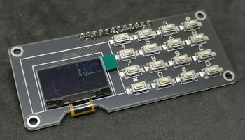
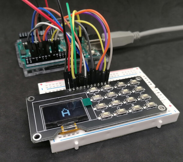
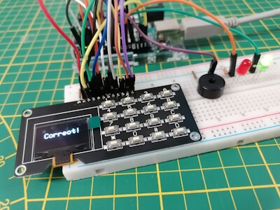
Das Modul habe ich auf aliexpress.com gefunden und fand dieses gleich sehr praktisch, da man damit recht einfach zum Beispiel einfache Passwort abfragen, generieren oder Daten Seitenweise anzeigen lassen kann.
Modul - OLED Display mit 4x4 Tastenfeld
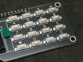
4x4 Tastenfeld
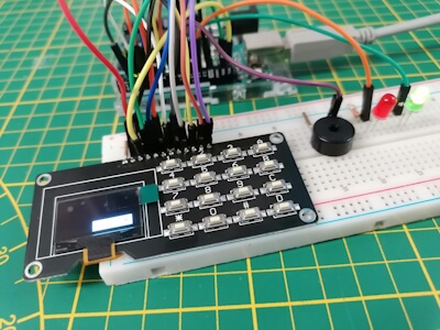
Aufbau des Moduls - OLED Display mit 4x4 Tastenfeld
Das Modul verfügt wie erwähnt über ein OLED Display von 0,96" sowie über ein 4x4 Tastenfeld, welches die Zahlen von 0 bis 9 und die Buchstaben A bis D, sowie die Sonderzeichen * und # darstellt.
Technische Daten
Bevor wir in das Beispielprojekt eintauchen, lohnt sich ein Blick auf die technischen Spezifikationen des OLED Displays. Das Tastenfeld verfügt über keine spezifischen Daten, daher werden diese nicht aufgeführt.
Abmessung80 mm x 37 mmLochdurchmesser3 mmOLED DisplayTreiberchipSSD1315SchnittstelleI2CAuflösung128x64Displaygröße0,96 Zoll (2,44 cm)FarbeAbmessungen24,7 mm x 27 mm
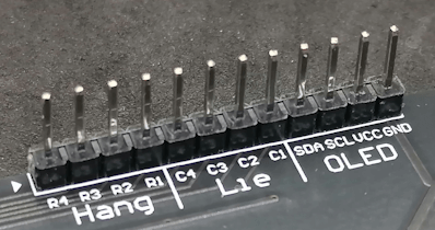
Pinout des Moduls
Das Modul hat 12 Pins, welche auf der Rückseite beschriftet sind. Diese sind aufgeteilt in OLED für die Pins des OLED-Displays sowie in Hang & Lie. Wobei ich denke das dieses in chinesisch für Zeile & Spalte steht.
Stiftleiste für den Anschluß an den Mikrocontroller
Eine 4x4 Matrix Tastatur habe ich dir bereits im Beitrag Arduino Lektion 68: 4×4 Matrix Tastatur vorgestellt. Diese hier verbaute Tastatur ist sehr ähnlich.
Hinweis von mir: Die mit einem Sternchen (*) markierten Links sind Affiliate-Links. Wenn du über diese Links einkaufst, erhalte ich eine kleine Provision, die dazu beiträgt, diesen Blog zu unterstützen. Der Preis für dich bleibt dabei unverändert. Vielen Dank für deine Unterstützung!
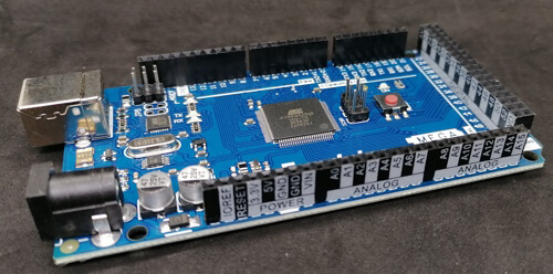
Wenn du noch weitere Komponenten an deinen Mikrocontroller anschließen möchtest (oder musst) dann empfehle ich dir den Arduino Mega 2560 R3 dieser hat deutlich mehr Pins als der UNO R3 und somit vielseitiger.
Funduino MEGA 2560 R3 - Buchsenleisten mit Pinbeschriftungen
Das Modul habe ich wie folgt an den Arduino UNO R3 angeschlossen:
Pin BeschriftungArduino UNO R3ZeilenR4digitaler Pin D9R3digitaler Pin D8R2digitaler Pin D7R1digitaler Pin D6SpaltenC4digitaler Pin D2C3digitaler Pin D3C2digitaler Pin D4C1digitaler Pin D5OLED DisplaySDASDA oder analoger Pin A4SCLSCL oder analoger Pin A5VCC3.3 VGNDGND
Programmieren des Moduls in der Arduino IDE
Zum Programmieren des Arduino UNOs verwende ich die Arduino IDE 2.3.2 welche du unter https://www.arduino.cc/en/software kostenfrei herunterladen kannst. Zusätzlich benötigst du noch zwei Bibliotheken, um mit dem Display und dem 4x4 Tastenfeld arbeiten zu können.
Im oben verlinkten YouTube-Video wird ausführlich erklärt, wie das Modul korrekt angeschlossen und in der Arduino IDE programmiert wird. Alternativ kannst du den Programmcode auch direkt hier herunterladen.
Das Modul lässt sich super einfach als Eingabefeld für eine Passwortabfrage nutzen. Die Komplexität ist durch die möglichen Eingaben von 0 bis 9 und A bis D beschränkt, jedoch reicht dieses ja auch für eine geringe Sicherheit aus.
A new graphics tablet from Wacom is available. This has an OLED that produces a vibrant colour display and can be utilised on the go. The pen can handle a wide range of pressure. The Wacom Movink 13 is the first professional OLED graphics display, according to the company. It is intended to generate images and graphics with extreme precision and quality. It is compatible with an input pen. The Wacom Pro Pen 3 has three side buttons, a tilt angle, and recognition for 8,192 pressure levels. The parallax should be as little as possible. A unique Movink version of the Wacom Pro Pen 3 is included, which incorporates a tip holder that doubles as a tip remover.
It has an OLED display with a diagonal screen size of 13.3 inches. It should therefore provide exceptionally good black and colour reproduction. Aim for 95% of the Adobe RGB colour space and complete reproduction of the DCI-P3 colour space. Support for display calibration is provided; this is crucial when creating artwork that will be properly printed.
Because the delay is limited to less than one millisecond, usage ought to be especially convenient. The system is especially ideal for persons who are constantly on the go because it only weighs 420 grammes and is only 6.5 millimetres thick at its thickest. The USB Type-C cable is used to connect the system. The narrow display edge has touch keys that may be customised, which should improve workflow productivity.
Overview: An Examination of the Wacom Movink 13
Digital art and graphic design are changing swiftly, and the Wacom Movink 13 is a remarkable example of originality and innovation. This cutting-edge tool has altered how designers, artists, and hobbyists use their digital canvas. They thoroughly assess the Wacom Movink 13’s features, functionality, and user experience to show why it’s crucial for visual artists.
Design and Construction Quality: Combining Form and Function The Wacom Movink 13’s sleek, modern design attracts attention. This elegant, well-made device is lightweight and portable. The skillful integration of high-quality materials ensures longevity, making it ideal for studio or vacation use. The Wacom Movink 13’s ergonomic design and user-friendly layout improve comfort and efficiency by adapting to the user’s workflow.
Performance and Usability: Boosting Innovation Potential The real beauty of the Wacom tablet Movink 13 is found in its unparalleled usefulness and performance, which go far beyond its visual attractiveness. With its cutting-edge pressure sensitivity and tilt recognition capabilities, this device offers unmatched precision and control. Because of the Wacom Movink 13 fluid and responsive design, users can confidently unleash their creativity when creating elaborate designs, retouching images, or illustrating fascinating artwork. Furthermore, users may easily navigate complex projects with customisable shortcut keys and touch gestures, freeing them up to concentrate on their craft without interference.
High-quality and precise colour displays: Bringing Art to Life A key component of the Wacom Movink 13 experience is its exquisite colour accuracy and display quality. With its sharp colours and crystal-clear high-resolution screen, every stroke and detail is reproduced with accuracy and authenticity. Artists can rely on accurate reproduction of their ideas, whether they are working on bright images or delicate gradients, which enables smooth transitions between digital and traditional media. The Wacom Tablet Movink 13 guarantees accurate representation of every hue through its wide colour gamut support and professional-grade calibration, offering a lifelike viewing experience that enhances the creative process.
Software Compatibility and Integration: Easily Added to Your Workflow The Wacom Movink 13’s smooth integration with a variety of programmes and applications is one of its main advantages. Adobe Photoshop, Illustrator, and Clip Studio Paint allow users to achieve their creative visions using familiar tools and procedures. The Wacom Movink 13 lets users unleash their creativity in photo retouching, illustration design, and character animation with unequalled versatility and freedom.
Putting Money Into Creativity for Pricing and Value Proposition Even while the Wacom Movink 13 requires a substantial financial commitment, its benefits are indisputable. Due to its broad feature set, great performance, and long-lasting quality, this gadget offers a compelling ROI for professionals and enthusiasts. The Wacom Tablet Movink 13 offers an affordable alternative to conventional art supplies and equipment that improves output quality, streamlines workflows, and increases productivity. Furthermore, users can be guaranteed that their investment will continue to yield returns for many years to come with frequent software updates and continuous support.
In summary, embracing creativity and innovation To sum up, the Wacom Movink 13 is a digital drawing tablet that opens up a world of creative expression that is boundless. This gadget opens up new possibilities for artists, designers, and enthusiasts to push the frontiers of their trade and explore thanks to its flawless design, unmatched performance, and seamless integration. For everyone embarking on an artistic journey, be they a novice or an experienced artist, the Wacom Movink 13 is an indispensable partner.
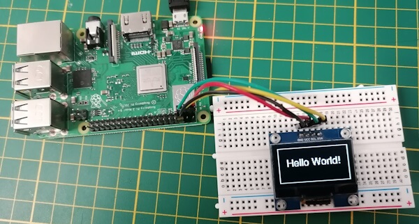
In diesem Beitrag möchte ich dir erläutern, wie du ein 1,3" OLED Display am Raspberry Pi via I2C & Python3 programmieren kannst. Die OLED Displays erhältst du für diverse Anwendungsfälle in verschiedenen Größen. Das 1,3" OLED Display ist hier besonders geeignet, dass dieses nicht nur günstig ist, sondern auch viel Platz für Text & Grafiken bietet.
In meinem Fall nutze ich den recht betagten Raspberry Pi 3B+, dieser ist etwas älter, aber für dieses und viele weitere Anwendungsfälle noch bestens geeignet.
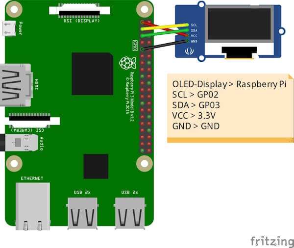
Aufbau der Schaltung - OLED Display via I2C am Raspberry Pi
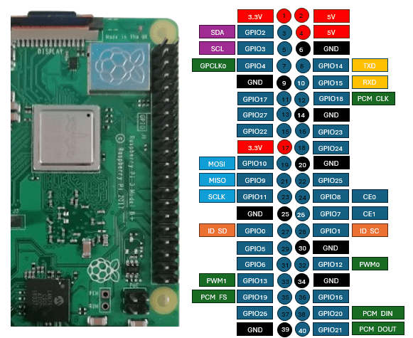
Als erstes schließen wir das OLED Display an den Raspberry Pi an. Wie erwähnt verwende ich den Raspberry Pi 3B+ welcher nachfolgendes Pinout hat.
Pinout des Raspberry Pi 3B+
Wenn du den neuen Raspberry Pi 5 verwendest, dann kannst du das Pinout ebenso verwenden, denn es ist mit dem 3er-Pi gleich.
Hinweis von mir: Die mit einem Sternchen (*) markierten Links sind Affiliate-Links. Wenn du über diese Links einkaufst, erhalte ich eine kleine Provision, die dazu beiträgt, diesen Blog zu unterstützen. Der Preis für dich bleibt dabei unverändert. Vielen Dank für deine Unterstützung!
Schaltung - Raspberry Pi mit OLED-Display am I2C Bus
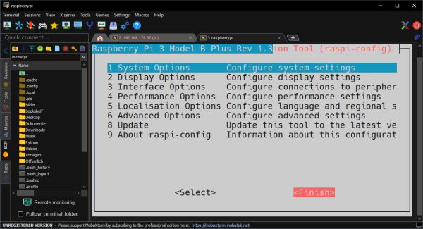
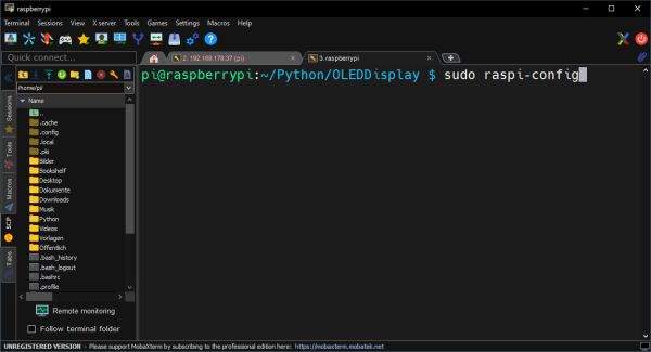
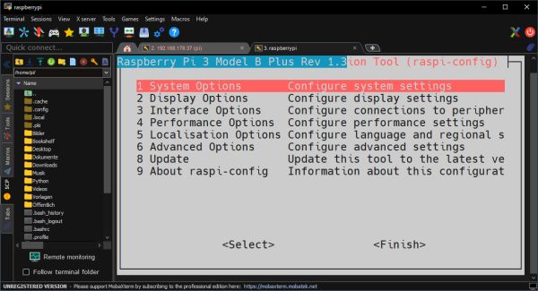
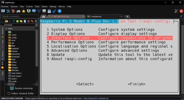
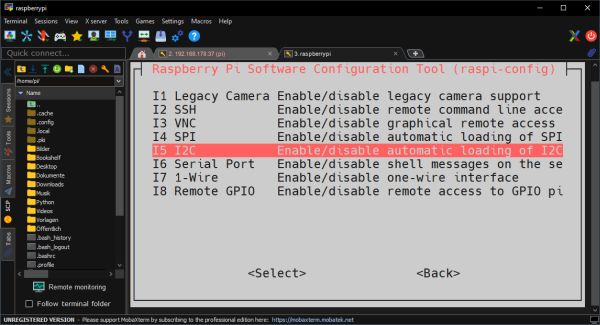
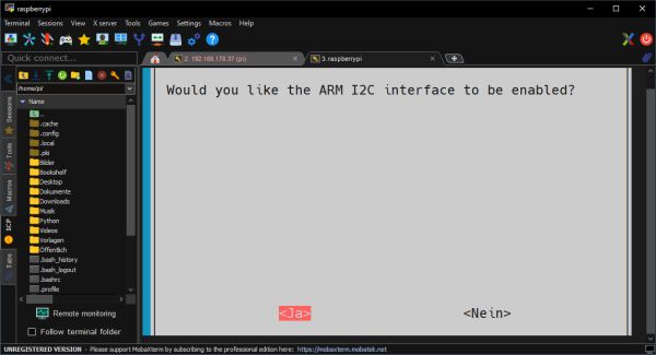
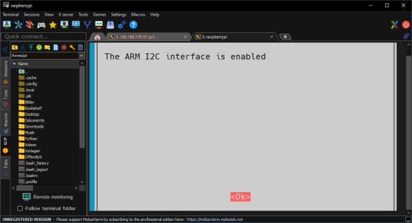
Bevor wir über der I2C Schnittstelle kommunizieren können, müssen wir diese zunächst aktivieren. Dazu starten wir die Konfiguration mit dem Befehl “sudo raspi-config”.
Durch die Menüs kannst du dich mit den Pfeiltasten auf der Tastatur bewegen. Deine Auswahl bestätigst du jeweils immer mit der Enter-Taste.
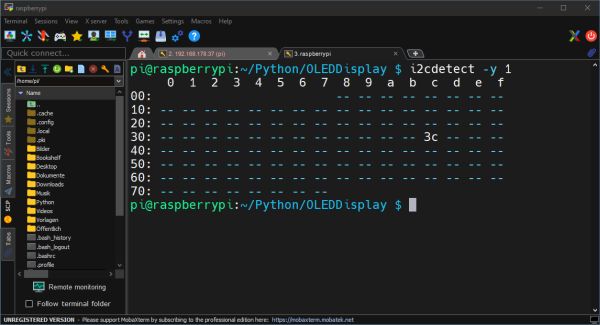
Wenn jetzt die I2C Schnittstelle aktiviert wurde, kann nun im nächsten Schritt nach Geräten gesucht werden. Zum Suchen von I2C Geräten am Raspberry Pi können wir das Kommandozeilentool i2cdetect wie folgt aufrufen:
i2cdetect -y 1
Die Zahl 1 repräsentiert in diesem Fall den I2C Bus, an welchem gesucht werden soll. Die Ausgabe ist dann eine Tabelle, aus welcher wir die gefundenen Adressen ablesen können.
Installieren der benötigten Module
Bevor wir mit dem Programmieren beginnen können, müssen wir ein paar Module auf dem Raspberry Pi installieren.
Wichtig ist, dass wir am Ende eine Zeit x warten, damit der Inhalt des Displays angezeigt wird. Es wird beim Beenden des Programmes der Bildschirminhalt geleert!
Ausgabe von “Hello World!” auf einem OLED-Display am Raspberry Pi
Alternativ können wir auch um den Block “with canvas…” eine Endlosschleife starten und auf ein Abbrechen durch die Tastenkombination Strg+C warten.
import time
from luma.core.interface.serial import i2c, spi, pcf8574
from luma.core.interface.parallel import bitbang_6800
Wenn wir jetzt das Programm wie gewohnt mit “python3 ” starten, sollten wir auf dem Display die Ausgabe sehen. Das Programm können wir jetzt jederzeit mit der Tastenkombination Strg+C abbrechen.
Einrichten einer Grußbotschaft beim Starten des Raspberry Pi
Den Raspberry Pi kannst du auch ohne Display & Tastatur verwenden. Da bietet sich das kleine Display an, um Informationen anzuzeigen, wenn dieser gestartet wurde und einsatzbereit ist.
Ausführen des Python3 Skripts mit systemd
In meinem Fall erstelle ich einen neuen Service unter /etc/systemd/system mit:
Calling all tech enthusiasts in China! Mark your calendars because Realme has officially locked in a launch date for its highly anticipated GT Neo 6 SE smartphone. This mid-range powerhouse, slated to debut on April 11th, 2024, promises impressive performance, a stunning display, and a sleek design – all at a competitive price point.
Let’s delve deeper into what we know so far about the Realme GT Neo 6 SE and why it might be your next smartphone upgrade.
Realme GT Neo 6 SE Charges
Mark Your Calendars: Launch Date and Availability
The official launch for the Realme GT Neo 6 SE is set for April 11th, 2024, at 2:00 PM China Standard Time (CST), which translates to 11:30 AM India Standard Time (IST). If you’re eager to witness the unveiling, you can tune in to the live stream on Realme’s official Weibo account.
Pre-orders for the Realme GT Neo 6 SE have already begun in China, indicating strong anticipation for this upcoming device. While a global launch date hasn’t been confirmed yet, the phone’s impressive features suggest it has the potential to resonate with a wider audience.
Powering Performance: A Look Under the Hood
The Realme GT Neo 6 SE boasts the Qualcomm Snapdragon 7+ Gen 3 chipset, which the company promotes as a “miniaturized version” of the flagship Snapdragon 8 Gen 3 SoC. This translates to robust performance capabilities perfect for everyday tasks, smooth multitasking, and even handling demanding games.
To further enhance thermal management and prevent overheating under heavy load, the Realme GT Neo 6 SE incorporates a large 10014mm² vapor chamber cooling system. This innovative cooling solution ensures sustained peak performance during extended use.
A Display Built for Entertainment: Captivating Visuals
Realme isn’t holding back on the display front either. The GT Neo 6 SE features a stunning 6.78-inch BOE 8T LTPO panel with a 1.5K resolution. This translates to sharp visuals, vibrant colors, and exceptional clarity for an immersive viewing experience.
But the display’s capabilities extend beyond resolution. The GT Neo 6 SE boasts a peak brightness of a staggering 6,000 nits, making it easily viewable even under direct sunlight. Additionally, it supports an adaptive refresh rate that can fluctuate between a smooth 120Hz for fast-paced action and a power-saving 0.5Hz for static content.
The display further enhances the user experience with 2160Hz PWM dimming technology that minimizes screen flickering and eye strain during extended viewing sessions. Gamers will especially appreciate the phone’s 2500Hz touch sampling rate, ensuring near-instantaneous touch response for precise in-game controls. To elevate the gaming experience further, the GT Neo 6 SE incorporates Super HDR technology, promising vibrant and realistic visuals in compatible games.
Design Aesthetics: A Sleek and Modern Look
Based on official teasers, the Realme GT Neo 6 SE appears to embrace a sleek and modern design language. The phone comes in a captivating “Liquid Silver Knight” color option, featuring a matte AG glass back panel for a premium and fingerprint-resistant feel.
The design is further accentuated by a contrasting metallic textured frame, adding a touch of sophistication. The rear camera module is adorned with a stainless-steel lens ring, enhancing the overall aesthetic appeal. Despite its premium materials, the Realme GT Neo 6 SE manages to remain remarkably lightweight, tipping the scales at a mere 191 grams.
Camera System: Capturing Life’s Moments
While complete details about the camera system are yet to be revealed, official teasers confirm a dual-camera setup on the rear of the Realme GT Neo 6 SE. The primary sensor boasts a resolution of 50 megapixels and supports Optical Image Stabilization (OIS) for sharper and clearer photos, especially in low-light conditions.
More information about the secondary sensor and the front-facing camera for selfies and video calls is expected to be unveiled during the launch event.
Battery Life and Charging (Speculative)
While official details about the battery capacity and charging capabilities haven’t been confirmed, considering Realme’s track record, we can expect a long-lasting battery paired with fast-charging technology. Previous Realme GT series phones have offered impressive battery capacities and rapid charging speeds, so it’s safe to assume the GT Neo 6 SE will follow suit.
FAQs
Q: When will the Realme GT Neo 6 SE be launched?
A: The official launch date for the Realme GT Neo 6 SE in China is set for April 11th, 2024, at 2:00 PM CST (11:30 AM IST).
Q: What are the key features of the Realme GT Neo 6 SE?
A: The key features include the Snapdragon 7+ Gen 3 chipset, a stunning 6.78-inch 1.5K display with a 120Hz refresh rate and 6,000 nits peak brightness, a dual rear camera system with a 50MP primary sensor, and a sleek design with a matte AG glass back.
Q: Will the Realme GT Neo 6 SE be available globally?
A: While a global launch date hasn’t been confirmed yet, the phone’s impressive features suggest it has the potential to be released in other markets.
Poco X6 Neo to Make Mark, Poco F6 Anticipation Grows
Poco X6 Neo The Poco X6 Neo is a new smartphone that Poco plans to release in India. The smartphone will be the brand’s first device to be released in 2024 with Neo branding. Our source said that the smartphone’s design is its greatest feature and that it is aimed mostly at Gen Z users.
Smartphone Arrival Launch Details and Price for the Poco X6 Neo in India Confirmed Our industry sources claim that the business plans to introduce the Poco X6 Neo in India by the end of next week. The next smartphone may come in several RAM and storage capacities and would cost less than Rs. 16,000.
Poco X6 Neo Live Photos and Important Details Disclosed Additionally, we managed to get pictures of the Poco X6 Neo that show off the rear panel’s design. The phone will come in Orange color variants. Poco branding is located on the left side of the elevated camera module at the top of the phone. Key specs of the phone are probably going to be comparable to those of the newly released Redmi Note 13R Pro variant.
Like the Redmi Note 13R Pro, the rear panel has an intriguing pattern and a flat shape. The photos verify that an LED flash and a dual camera configuration will be included in the Poco X6 Neo. Volume and power buttons are on the left.
The gadget will include a 108-megapixel rear camera. The phone will have a 5,000mAh battery. Having stated that, we may accept the formal declaration on the impending debut in India.
Poco X6 Neo Anticipated Features The Poco X6 Neo may include features and specs that are comparable to those of the Redmi Note 13R Pro, according to earlier sources. The smartphone was just released in China. When introduced in India, the Poco X6 Neo should offer similar features.
Pulse width modulation dims Redmi Note 13R Pro’s 6.67-inch OLED display at 2,160 Hz with 1,080×2,400 pixels and 120 Hz refresh rate. MediaTek Dimensity 6080 SoC has 256GB storage and 12GB RAM. It sports a 2-megapixel secondary camera and 108-megapixel primary camera. Front 16-megapixel cameras capture selfies. A side fingerprint sensor verifies the phone.
When is the Poco X6 Neo expected to launch? By March 2024, the Poco X6 Neo is anticipated to be on sale in India.
Is the Poco X6 Neo a new phone? Leaks imply that the X6 Neo is a repackaged Redmi Note 13R Pro that was introduced in China in November 2023, while this has not been officially verified.
What operating system will the Poco X6 Neo run? It is anticipated to be powered by MIUI 14 on top of Android 13.
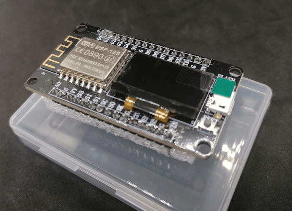
Willkommen zu meinem Technikblog, wo ich heute den Ideaspark ESP8266 in Kombination mit einem 0,96 Zoll (2,44 cm) OLED Display vorstelle. In diesem Beitrag wirst du eine Schritt-für-Schritt-Anleitung zur Programmierung dieses vielseitigen Mikrocontrollers finden.
Die Idee für diesen Beitrag entstand, nachdem ein aufmerksamer Leser mir seine Herausforderungen bei der Verwendung dieses Mikrocontrollers geschildert hat. Als Unterstützung für die Community habe ich daraufhin den Ideaspark ESP8266 mit dem 0,96 Zoll (2,44 cm) OLED Display erworben und innerhalb von 14 Tagen erhalten. Nun möchte ich mein erworbenes Wissen teilen und anderen dabei helfen, dieses faszinierende Hardware-Projekt erfolgreich umzusetzen.
Den Mikrocontroller bekommst du günstig auf ebay.de für derzeit knapp 8 € inkl. Versandkosten. Aber auch auf aliexpress.com und anderen Plattformen aus dem asiatischen Raum findest du diesen recht günstig, jedoch mit deutlich längeren Lieferzeiten.
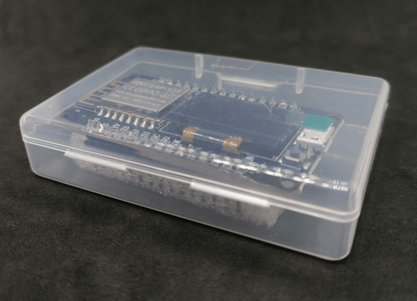
Lieferumfang
Bei meinem Paket war lediglich der Mikrocontroller in einer kleinen Plastikschale enthalten, du musst dir somit noch ein passendes Micro-USB-Kabel in entsprechender Länge kaufen.
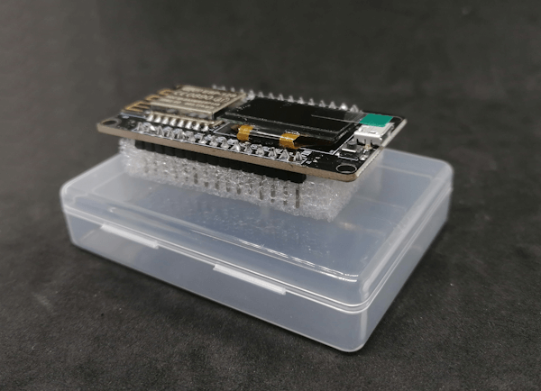
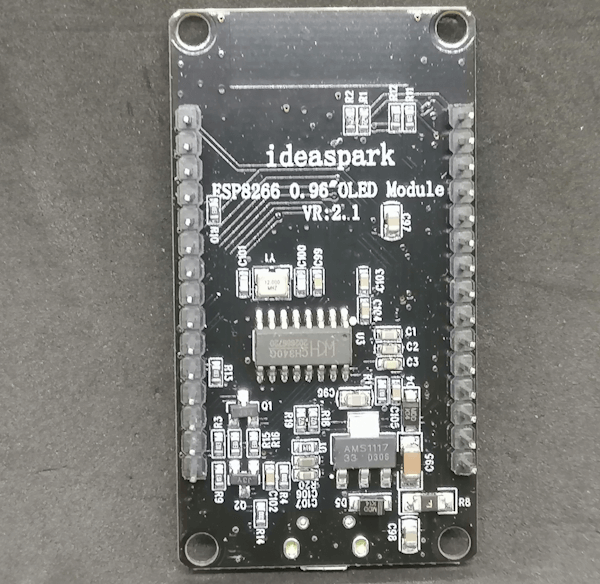
Aufbau des Mikrocontrollers
Was besonders ins Auge fällt, ist das OLED Display, welches diesen Mikrocontroller, wie ich finde, besonders aufwertet.
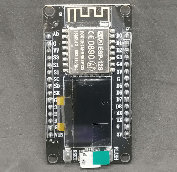
ESP8266 von Ideaspark (Vorderseite)
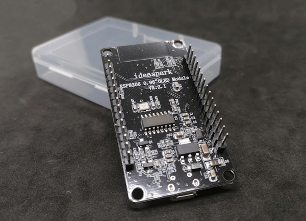
ESP8266 von Ideaspark (Rückseite)
Eigenschaften des 0,96" OLED Displays
Kommen wir zunächst zu den technischen Daten des OLED-Displays:
- Größe: 0,96 Zoll (2,44 cm),
- Farbe: Gelb & Blau,
- Treiber: SSD1306,
- Betriebsspannung: 3.3V bis 5V,
- Betriebstemperatur: -30 °C bis 70 °C,
- Abmessung: 27 mm x 27 mm x 4 mm,
- Auflösung: 128 x 64 Punkte
Das verbaute OLED Display ist über I2C über die nachfolgenden Pins angeschlossen:
I2C PinGPIOPin NummerSDAGPIO126SCLGPIO145
Anschluss an den Computer
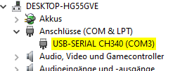
Schließen wir jetzt einmal den Mikrocontroller mit einem Micro-USB-Kabel an den Computer an. Ich verwende ein Microsoft Windows 10 (mit aktuellen Updates) und dieser wird sogleich als “USB-SERIAL CH340” erkannt (siehe Grafik).
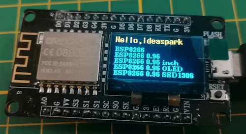
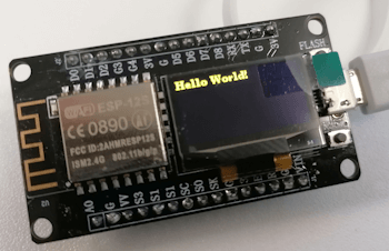
Zeitgleich wird auf dem Display ein Text in gelb / blauer Schriftfarbe angezeigt.
Beispielprogramm auf dem ESP8266 mit OLED Display von Ideaspark
Einrichten des ESP8266 in der Arduino IDE
Damit wir diesen Mikrocontroller mit unseren Programmen bespielen können, müssen wir den Boardtreiber installieren. Für den Boardtreiber wiederum müssen wir noch eine Quelle für diesen anlegen und genau das machen in den nächsten Schritten.
Schritt 1 - Quelle für den Boardtreiber eintragen
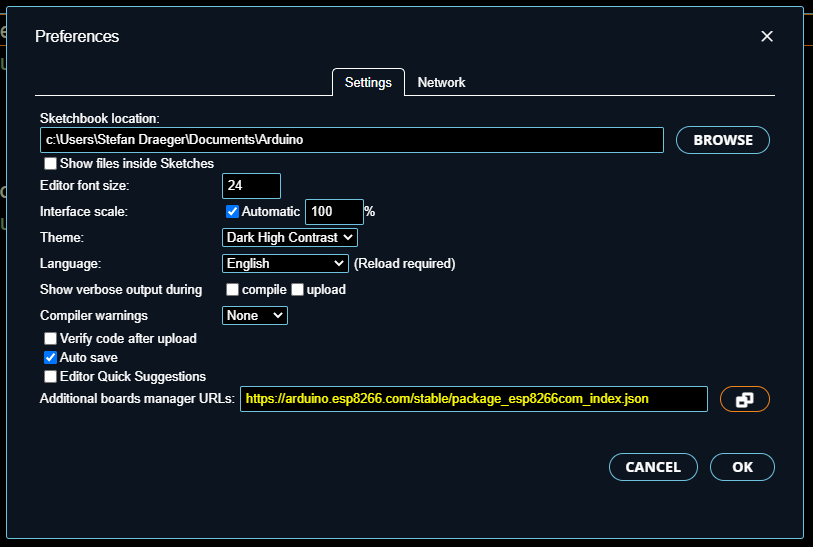
Im ersten Schritt müssen wir eine zusätzliche Quelle für den Boardtreiber in den “Zusätzlichen Boardverwalter URLs” eintragen.
Schritt 2 - Installieren des Boardtreibers über den Boardverwalter
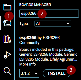
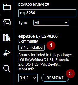
Zum installieren des Boardtreibers öffnen wir den Boards Manager über das Icon links (1) und suchen dann nach “esp8266” (2) in meinem Fall wurde nur ein Eintrag gefunden “esp8266 by ESP8266 Community” an welchem die Schaltfläche “INSTALL” (3) betätigt wird.
Wenn der Vorgang abgeschlossen ist, sollte der Text “ installed” (4) sichtbar werden und die Schaltfläche “INSTALL” zu “REMOVE” (5) ändern.
Schritt 3 - validieren der Installation
Im Abschluss spielen wir nun ein kleines Programm auf den Mikrocontroller, um zu testen, ob die Installation korrekt verlaufen ist.
#define led BUILTIN_LED
void setup() {
//beginn der seriellen Kommunikation mit 9600 baud
Serial.begin(9600);
//definieren das der Pin der BUILTIN_LED als Ausgang dient
pinMode(led, OUTPUT);
}
void loop() {
//Ausgeben des Textes “Hallo Welt!” auf der seriellen Schnittstelle
Serial.println(“Hallo Welt!”);
//aktivieren der LED
digitalWrite(led, HIGH);
//einlegen einer Pause von 500 Millisekunden
delay(500);
//deaktivieren der LED
digitalWrite(led, LOW);
//einlegen einer Pause von 500 Millisekunden
delay(500);
}
Programmieren des ESP8266 von Ideaspark
Nachdem der Treiber für den ESP8266 installiert wurde und wir geprüft haben, dass dieser korrekt arbeitet, können wir mit der Programmierung beginnen. Da dieser Mikrocontroller bereits über ein OLED Display verfügt, wollen wir jetzt mit einem Beispiel dazu starten.
Installieren der Bibliothek u8g2 für das OLED Display
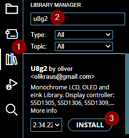
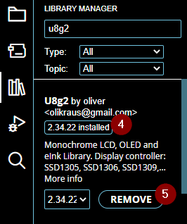
Damit wir das verbaute OLED Display via I2C programmieren können, müssen wir zunächst eine Bibliothek installieren. Ich wähle hier u8g2 aus. Dazu klicken wir links auf den “Library Manager” (1) und suchen danach “u8g2” (2) aus den Suchergebnissen wählen wir im Eintrag “U8g2 by oliver” die Schaltfläche “INSTALL” (3) aus.
Wenn der Vorgang abgeschlossen ist, dann wir hier der Text “ installed” (4) angezeigt und die Schaltfläche “INSTALL” ändert sich zu “REMOVE” (5).
Die Bibliothek u8g2 habe ich bereits in einigen anderen Beiträgen verwendet, ein großer Vorteil ist, dass diese recht klein ist und somit noch viel Speicher auf dem Mikrocontroller für das eigentliche Programm verbleibt.
Beispiel - “Hello World!” auf dem OLED Display ausgeben
Wenn die Bibliothek installiert wurde, können wir nachfolgendes kleines Programm auf dem Mikrocontroller ausführen und es sollte dann die Textzeile “Hello World!” angezeigt werden.
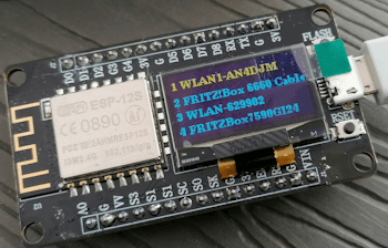
Beispiel - Ausgeben von WiFi Netzwerken auf dem Display
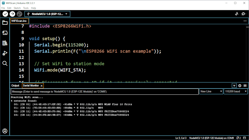
Wollen wir nun mit der WiFi Schnittstelle nach vorhandenen Netzwerken suchen und diese dann auf dem Display ausgeben. Als Grundgerüst nutze ich hier zunächst das Beispiel aus der ESP8266 Bibliothek WiFiScan, denn dieses erzeugt bereits die Ausgabe auf der seriellen Schnittstelle.
Ausgabe des Beispieles WiFiScan aus den ESP8266 Beispielen
Dieses müssen wir jetzt noch um die Ausgabe auf dem Display erweitern.